Calculation of inductance coils with ferromagnetic cores
When using closed-loop ferromagnetic cores, almost the entire magnetic flux is concentrated inside such a core. In this case, to simplify calculations, the concept of a magnetic circuit is introduced. The laws and concepts for a magnetic circuit, such as magnetomotive force, magnetic resistance, etc., are very similar to the corresponding laws and concepts for an electric circuit. This correspondence follows from the obvious fact that both the magnetic and electric fields are two facets of a single and indivisible entity: the electromagnetic field.
Magnetic cores can have a wide variety of forms. To simplify calculations, any such core is substituted by an ideal toroidal core. The core that has the same electrical parameters and has the same number of turns as the original one. It is assumed that the following conditions are met:
- The all magnetic flux is concentrated inside such a core;
- There is no magnetic field outside the core and gap;
- In the non-magnetic gap (if there is one), the magnetic flux is exactly the same as inside the core;
- The magnetic flux in the cross-section of such a core is distributed uniformly;
- The magnetic induction vector is always perpendicular to the cross-section of the magnetic circuit, then we can turn from vector to scalar values;
- The cross-section of the magnetic circuit is constant along its full length;
You need to understand that such a core do not exist in reality; it's an abstract object. The parameters of the magnetic circuit of such a substituting abstract core are called effective:
- Effective magnetic circuit length le;
- Effective cross-section of the magnetic circuit Ae;
- Effective core volume Ve = le * Ae;
To take into account the influence of the gap in the magnetic circuit, the core with a gap is substituted by a fully ideal virtual core without a gap with the same number of turns, but with less permeability. The magnetic permeability of such a core is called effective magnetic permeability µe:
 |
[1] |
where µr is relative magnetic permeability of the core. When the coil operates in the initial part of the magnetization curve, this value can be taken equal to the initial magnetic permeability of the core material µi.
For such an ideal core, the following relations are valid:
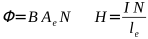 |
[2] |
where:
- Φ : magnetic flux [Wb];
- B : magnetic induction [T];
- H : magnetic field strength [A/m];
- Ae : effective cross-sectional area of the magnetic circuit [m2];
- le : effective length of magnetic circuit [m];
- N : numbers of turns;
- I : current strength [A];
Based on these relationships and the basic formulas of the theory of magnetism, we can find the inductance of a coil with the such ideal core:
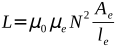 |
[3] |
where:
- L : inductance [H];
- µ0 = 4 π · 10-7 : magnetic constant [H/m];
- µe : effective magnetic permeability of the core;
- N : numbers of turns;
- Ae : effective cross-sectional area of the magnetic circuit [m2];
- le : effective length of magnetic circuit [m];
If the value of the saturation induction of the core material Bs (or Bmax) is known from the datasheets, then the saturation current can be determined:
 |
[4] |
where:
- Is : saturation current [A];
- Bs : saturation magnetic induction [T];
- le : effective length of magnetic circuit [m];
- µ0 = 4 π · 10-7 : magnetic constant [H/m];
- µe : effective magnetic permeability of the core;
- N : numbers of turns;
For nickel-zinc ferrites Bs = 0.2...0.3 [T], for manganese-zinc ferrites Bs = 0.3...0.5 [T], for steel and iron Bs = 1...2 [T]. Often in datasheets for ferrite cores, the magnitude of magnetic induction is measured in units of [Gauss]. The following relation is valid: [T] = [Gs] * 10-4.
Frequently in the datasheets of ferrite cores you can find a parameter: the inductance factor of the core AL. It is designed to simplify the calculation of inductance, and it is calculated using a short formula:
 |
[5] |
where:
- L : inductance [nH];
- AL : inductance factor [nH/(turn)2];
- N : number of turns;
There is no single agreement on the units of measurement of the inductance coefficient; each manufacturer sets its own standards, but the most commonly seen units have the same value:
[nH/(turn)2] = [mH/(1000 turns)2].
If the effective parameters of the core and its inductance factor are known from the datasheets, then its effective magnetic permeability can be calculated (for example, to calculate the saturation current):
 |
[6] |
where:
- µe : effective magnetic permeability of the core;
- AL : inductance factor [nH/(turn)2] or [mH/(1000 turns)2];
- le : effective length of magnetic circuit [mm];
- Ae : effective cross-sectional area of the magnetic circuit [mm2];
Also, if we know the relative (initial) magnetic permeability of the core material, using formula [1] as a basis, we can determine the value of the non-magnetic gap of the core
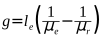 |
[7] |
where:
- g : non-magnetic gap size [mm];
- le : effective length of magnetic circuit [mm];
- µe : effective magnetic permeability of the core;
- µr : relative magnetic permeability of the core;
Typically, in educational materials devoted to the calculation of magnetic circuits, a drawing of a U-shaped core is presented as a clear example. In this case, the illusion may arise that it is enough to pick up a ruler and measure the length and cross-sectional area of the magnetic circuit directly on the real core. This, let’s say, is not always true, since in a real core condition 6) may not be met. Even a real toroidal core has to be replaced with an ideal one, since in a real one, condition 4) is not met. Based on the physical dimensions of a real core, special constants C1 and C2 are calculated for it, through which the effective parameters for such a core are calculated. A detailed analysis of such calculations is presented in the help section of the site:
- Calculation of a coil on a toroidal core (real, not ideal);
- Calculation of a coil in a pot core;
- Calculation of a coil on a U-shaped core;
- Calculation of a coil on a E-shaped core;
- Calculation of a coil on an RM core;