Metal detector search coil

O-coil
A metal detector's multi-turn circular wire coil can be represented as a multilayer inductor with a square winding cross-section. This coil belongs to the class of “short coils.” The well-known simple Wheeler formula is unsuitable for calculating such coils; more details are available in the article “Calculating Multilayer Inductors.” To calculate a metal detector search coil, we can use a numerical calculation method based on Maxwell's formula, which is used in the main program module. In other words, simply select the “Multilayer Coil” option. However, considering that the coil thickness is much smaller than the winding diameter, we can simplify the calculations by using the so-called “single solid turn method.” In this case, the inductance of a single turn with a diameter equal to the multi-turn coil's thickness is calculated. Multiplying this by the square of the number of turns yields the inductance of the multi-turn bundle. J.C. Maxwell was the first to derive a simple formula for calculating such a coil: где:
- L: inductance (nH);
- r: average winding radius (cm);
- R: geometric mean distance of the bundle cross-section (cm);
- N: number of turns;

 Later in 1916, this formula was improved for more accurate calculations in the work of Rosa. A more understandable version of the Rosa's formula was published in 1931 by Brooks. See the web-links below. The Brooks formula is suitable to calculate the “Short” and “Medium” multilayer coils.
The Brooks formula was reduced to the modern form by George Overton in the book "Inside the Metal Detector".
 |
[1] |
где:
- L: inductance (H);
- r: mean radius of the winding (half of the Dm) (m);
- l: length of the winding that is equal to the winding thickness T (m);
- N: number of turns;
The book has the calculation algorithm that is based on this formula, which we use in our open source Coil64 program with the kind consent of George Overton.
In the Coil32 program we use another variant of the same formula. So the results of the calculation by the both program are quite close.
 DD coil
The D-coil calculation can be done in several different ways:
- Represent the winding shape of the “solid turn” as an equivalent ellipse. Knowing the major and minor axes of this ellipse, its self-inductance can be calculated using elliptic integrals.
- Substitute the D-coil with an equivalent round coil and calculate it using formula [1]. In this case, we got a question of choosing an equivalent diameter for such a coil. For example, using the arithmetic mean of the major and minor axes of an ellipse. Alternatively, use a round coil with the same circumference as the D-coil's winding perimeter.
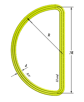
- Imagine the coil as a combination of two segments: a semicircle of radius R and a straight chord of length 2R. Knowing the self-inductance of each segment and the mutual inductance between them, we can calculate the total inductance of the D-coil. This calculation method uses Coil64.
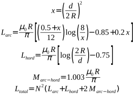
The calculation of the self-inductance of the segments and their mutual inductance, as well as the total inductance of the D-coil, is going using the following expressions:
 |
[2] |
где:
- Larc, Lhord, Ltotal: self-inductance of the segments of the semicircle and the linear chord, as well as the total inductance of the D-coil (H);
- Marc-hord: mutual inductance between segments of a semicircle and a linear chord (H);
- R: average radius of a semicircle segment (m);
- d: the thickness of the winding, which in the case of a square cross-section is equal to the thickness T (m);
- N: number of turns;
- μ0: magnetic constant 4π·10-7 [T·m / A];
- x: auxiliary dimensionless coefficient;
The program defines the wire bundle cross-sectional diameter as the diameter of an equivalent circle with the same area as a square with side T. Additionally, the program shows out the secondary parameters of the D-coil and the parameters of the TX and RX LC-circuits of the metal detector, which are necessary for its design. Since the real coil shape does not exactly correspond to the semicircle and chord model, the internal perimeter of the wire bundle is used as the input parameter for the calculation. It can be measured by pulling one turn of fiber or wire through the sensor body.
It's important to remember that the inductance of a real coil depends on many difficult-to-calculate factors, including the tightness of the wire bundle and the effect of the coil's encapsulation. Therefore, the calculation in the program should be considered only approximate.
Related links:
- Inside the Metal Detector: George Overton, Carl Moreland. The Second Edition, 2015, Appendix A. [p. 207, equation (A-2)];
- A Treatise on Electricity and Magnetism: J. C. Maxwell Vol. 2 §706.
- FORMULAS AND TABLES FOR THE CALCULATION OF MUTUAL AND SELF-INDUCTANCE: E. B. Rosa F. W. Grover, Sci. Paper #169, 1916.[p. 136, equation (86)];
- DESIGN OF STANDARDS OF INDUCTANCE: By H. B. Brooks, RP342, 1931.[p. 294, equation (2)];