How to calculate inductance?
 We can use different methods to calculate the inductance using numerical methods or handbook formulas. They can be conditionally divided into three levels:
- Calculation by simplified empirical formulas (Low level)
- Numerical method based on a simplified coil model (Intermediate level)
- Numerical method based on the fundamental laws of electrodynamics (High level)
Low level is an empirical approach that involves the selection (fitting) of relatively simple approximating formulas based on the results of measuring the inductance of real coils or by simplifying equations of a higher level. The calculation according to simplified empirical formulas has limitations in accuracy and is applicable only to coils with a certain winding geometry. Most of these formulas can be found here. Despite the low accuracy, such a calculation is most often quite sufficient in amateur radio practice. & nbsp;
Intermediate level is based on the fundamental formulas of physics applicable to circular filament conductors, developed in the 19th century by J.K. Maxwelland H.A. Lorentz. Allows you to calculate more accurately than by empirical formulas, but don't require excessive computer hardware resources. Disadvantages: Lower calculation accuracy compared to high level. Inability to calculate a coil with an arbitrary winding geometry. The coil must operate at frequencies well below its self resonance frequency.
High level is a calculation in programs based on the fundamental laws of classical electrodynamics, the so-called electromagnetic simulators. These include COMSOL Multiphysics, FEMM, ANSYS HFSS, GAL-ANA etc. These programs use special numerical methods such as moment method and finite element method. The calculation in such programs is quite accurate, it allows you to take into account many nuances, calculate an arbitrary-shaped coil, but it requires huge computer resources. It is used in scientific analysis or if the coil is operating in a mode where it cannot be represented as a lumped element.
Let's take a closer look at the intermediate level calculation example that Coil64 uses… The calculation of inductance in the Coil64 program is based on the Maxwell's model, in which the coil is represented as a set of coaxial infinitely thin circular conducting filaments. From Gauss's law it follows that the magnetic field force lines are always closed. It follows from this that the magnetic flux generated by a circular current circuit all passes through the surface bounded by this circuit. This circumstance is reflected in the following formula: 
From this formula, you can derive a definition for the intrinsic inductance of a circular conductor through the double contour integral of F.E. Neumann for mutual induction [see here]: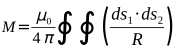
As shown by J.K.Maxwell, for two infinitely thin circular coaxial filaments, this integral has a unique solution, which looks like this:
 |
[1] |
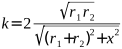

- M: mutual induction;
- r1, r2: radii of two infinitely thin circular conductors;
- x: the distance between the centers of the circles bounded by these conductors;
- K(k), E(k): complete elliptic integrals, respectively the first and second kind;
The numerical method of calculation using the Maxwell's formula is reduced to numerical methods for solving elliptic integrals.
Using the Maxwell's formula, one can calculate both the inductance of multilayer and single-layer coils, and the mutual inductance of two separate coils. Model errors associated with the assumption that the wire is infinitely thin and is a set of circular conductors (although in fact it is a spiral) can be reduced by appropriate corrections.
Calculating the mutual inductance of the conductor “on itself”, i.e., its self-inductance, Maxwell uses the concept: “geometric mean distance” — GDM (g), for a round wire:
g = e0.25*rw, where rw: wire radius.
The next point is very important. All of the above logic of reasoning and derivation of formulas, starting from the Neumann formula, is valid in the case of a uniform distribution of the current density along the coil. In the vast majority of practical cases, this is true. However, if the coil operates at frequencies near to the self resonance frequency, the uneven distribution of the current density along the conductor begins to appear! In other words, the dependence of the inductance on frequency begins to appear, which is not taken into account in our calculations. Therefore, the inductance of the coil can be calculated correctly only at frequencies not exceeding 60-70% of the self resonance frequency. Thus, Coil64 is not suitable for precise calculations, for example, Tesla coils or helical resonators. In this case, and if the coil operates above the self resonance frequency, it must be represented only as a transmission line model and calculated in electromagnetic simulators, or special empirical formulas should be used.
- An introduction to the art of Solenoid Inductance Calculation D W Knight 2013
- Numerical Methods for Inductance Calculation Robert Weaver 2012
- Inductance Calculation Techniques --- Part II: Approximations and Handbook Methods Marc T. Thompson 1999
- A new method for inductance calculation M.A.Bueno A K T Assis 1995