


Calculation of the multilayer inductor
 Most often in different soft and online calculators the multi-layer inductor is calculated by a simple empirical formula H.А. Wheeler:
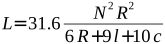
- L - inductance (µH)
- N - number of turns
- R - mean radius of the winding (m)
- l - length of winding (m)
- c -winding thickness (m)
In previous versions of Coil32 this formula was also used.
 But ... Any empirical formula not reflect the real physical phenomena and has limited accuracy of calculations. In this case the limit is quite serious. The Wheeler's formula with sufficient accuracy (± 1%) suitable for calculating only the coil with limited geometry of winding. What does this mean? This means that the cross section of the coil winding as possible must have a square shape. In other words, the winding length l should be about equal to the thickness of winding c. Moreover, as Wheeler writes in his paper, all three terms in the denominator should be about equal ( i.e. R ≈ l ≈ c). In addition we see that the formula does not take into account the thickness of the insulation of the wire, therefore 1% deviation increases significantly even with "friendly" to the formula winding geometry. The introduction of the so-called "packing factor" does not help the situation. In practice often we have to make quite long coil, winding length of which is significantly greater than the thickness and with a small number of layers. Such coils the formula calculates absolutely wrong. The limiting case where the multi-layer coil get down into a single layer. The calculation by the above formula gives absolutely wrong result!
Why, then, do enjoy this limited formula? We can divide the multi-layer coils into three large classes: short coils when R much more l, long coils when R much less l and medium ones when R close to l. Wheeler's coil is the simplest coil of the middle class. The very interesting is the question, "What is a geometry of the winding has maximum possible inductance for a given length of wire?" As a consequence - loss in that coil is also minimal, which is important, for example in the design of crossover inductors. In 1931, Brooks wrote a paper in which he calculated the ideal dimension values for a such optimal coil. The mean radius R has to be very close to 3c/2 and the winding needs to have square cross-section, in other words c has to be close to l. This optimal multi-layer coil is named the Brooks coil and also belongs to the middle class.
 Brooks has deduced the formula to calculate the optimal multi-layer coil:
 Where:
- L - inductance (H);
- R - mean radius of the winding (m);
- N - number of turns;
However, the Brooks formula is only suitable for calculating the Brooks coil. It also, like the Wheeler's formula, has limitations in winding geometry. The Brooks coil is used in audio system filters and we devoted a separate article to this.
Where is the solution of the problem? We can use the more accurate empirical formulas, such as published in the book "Radio Engineer's Handbook - 1943 F.M. Terman pp 60..63". Terman delivered a formula for short and long coils with the special calculated factors. We can also use other empirical formulas. But ... At first - we are again dealing with the empirical formula, which, because of its limitations somewhere again may be wrong, and secondly - such calculation method was acceptable in the middle of the XX century, when it was necessary to use a pencil and paper , tabular data, and column addition. In XXI century, when according to the Moore's law the computing power doubles every two years, we can take a more perfect universal algorithm that could be used for the calculating of the multi-layer coils with the any geometry of winding.
 This numerical method bases on the formulas that the physicist J.C. Maxwell has proposed in the late XIX century in his famous work - "A Treatise on Electricity and Magnetism." (Maxwell, James Clerk; "A Treatise on Electricity and Magnetism", Vol. 2, Third Edition, Dover 1954. Art. 701, "To find M by Elliptic Integrals", pp. 338-340.) Maxwell gives a formula for calculating the mutual inductance of two coaxial circular loops:

- M - mutual inductance,
- r1, r2 - radii of loops,
- k - factor depending on the distance between loops.
- K and E - elliptic integrals of the first and second kind.
This is the basic formula that displays real physics.
 A multilayer coil can be represented as a large number of coaxial circular filaments. Calculating the self-inductance of each turn, and mutual inductance of each possible pair of turns and summing it all, we get a self-inductance of the multilayer coil. Such a calculation under the force of modern computers. It is also necessary to consider an amendment to the fact that the real wire is not infinitely thin. Work on the creation of such a programming algorithm has been done by the Canadian radio-amateur Bob Weaver in 2012, as well as Brazilian fan of Tesla coils Dr. Antônio Carlos M. de Queiroz in 2005.
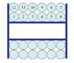 Calculation of the multi-layer air core coil in Coil64 is based on these decisions. It is assumed that the winding has the form as shown in the image.
- d is the diameter of the wire on copper;
- k - the diameter of the wire with insulation, or the distance between the centers of adjacent turns
 In Coil64 the turns of multi-layer coil are adding one by other. The self-inductance is calculated for each new turn and also the mutual inductance is calculated between this turn and all previous turns. The result is summed to total inductance. If the winding form is not the same as on figure, the calculation not will be correct. In this case it is easier to measure than to calculate and we can only estimate required number of turns for multi-layer coil.
Coil is "virtually wound" until the required inductance will be reached, the latter layer may be incomplete. Along the way, calculated the total length of the wire and its DC resistance. The same calculation algorithm is implemented in the multilayer coil online calculator. The application have possibility to calculate multi-layer air core inductors with insulating layers. On figure you can see the schema of winding of multi-layer coil with insulating pads. You can select number of the winding layers between insulating pads, for example two as on the figure.
 Unlike a single-layer coil, the self-capacitance of a multilayer coil is largely determined by the interturn capacitance between the winding layers. To reduce it, a multilayer coil is divided into separate sections. The inductance of such a sectioned multilayer coil is the sum of the inductances of the individual sections and the mutual inductances between all pairs of sections. In old handbooks, you can find formulas for calculating the mutual inductance between two multilayer coils. However, they are also not universal for different winding geometries and have low accuracy. The Coil64 program uses the algorithm described above to calculate a sectioned multilayer coil. First, it is determined how many turns can fit in a separate section and, with “software layer-by-layer winding” of the coil, the offset between the sections s is taken into account. In this case, since the total inductance is calculated as the sum of the self-inductances of each turn in all sections and the mutual inductances between any pair of turns, there is no need to calculate the mutual inductance between sections.
 The orthocyc winding differs from an regular one in the next layer turns fall into the grooves between the turns of the previous one. The cross-section of the coil has the appearance of a honeycomb structure. If with ordinal winding the distance between the centers of adjacent layers is equal to the diameter of the wire with the insulation, then in the case of orthocyclic winding this distance is smaller and is calculated from the properties of the equilateral triangle geometry. In this case, the winding to be denser and less thick. As the average turn diameter decreases, more turns are required to achieve the same inductance value as with regular winding. However, for the same reason, a shorter length of wire is required for winding. The relative position and number of turns in the even and odd layers of the orthocyclic winding may be different. The Coil64 application uses one of the layout options shown in the figure. Since in practice it is impossible to achieve such an ideal winding density and geometry, a margin should be given in the number of turns compared to the calculated one.
Audiophiles should not forget that the optimum coil is the Brooks coil.
References:
- Numerical Methods for Inductance Calculation - Robert Weaver 2012 (Part 1 –> Elliptic Integrals -> Multi-Layer Coils);
- Classical Calculation for Mutual Inductance of Two Coaxial Loops in MKS Units - Kurt Nalty 2011;
- Mutual Inductance and Inductance Calculations by Maxwell’s Method - Dr. Antônio Carlos Moreirão de Queiroz 2005;
- Coil winding technology - Wikipedia;


1) The calculation of the thickness of the coil (c). I believe it should be k*number of layers.
2) The necessary length of the wire. There are different results produced between the older version (9.8) and the newer version (10.0
Thank you. I'll be looking...
The errors have corrected.