


PCB inductors

 Flat PCB coils are most often used in the VHF and UHF bands to reduce the size of the device. Usually, they are produced with round, square or meander form of turns, although it can be in the form of a polygon. With the advent technology of multilayer PCB, the multilayer coil appears. The use of a magnetic core is ineffective because such a core is far away from the turns of the coil and can change its inductance by 3 - 5 %, which in most cases is not enough. Therefore, printed inductors are used in most cases when the adjustment is not required and the value of the inductance units does not exceed microhenry. Q-factor of PCB inductors is generally lowered then Q-factor of the inductors having a coil of wire and less than that of the cylindrical microstrip coils. The self-capacitance of the printed inductors depends on the width of the spiral turns, the gap between them and the PCB material and can reach 3 to 5 pF, which is pretty high at such frequencies. All I have said is not in favor of flat PCB coils, however, the compact design along with the use of SMD components often plays a decisive role in use such inductors.
You can use the online calculator to calculate the PCB coils on our site.
To compute inductance of PCB inductors we can use three pretty accurate methods.
1.The first approximation is based on a modification of an expression developed by H.A.Wheeler for the planar spiral inductors:
 |
[1] |
- L- inductance (µH);
- µ0 = 4π*10-7 - magnetic constant;
- N - number of turns;
- Davg - average diameter of coil (µm) (expression[4]);
- φ - fill factor (expression[4]);
- The coefficients K1 and K2 are layout dependent and are shown in the following table:
| Layout | K1 | K2 |
|---|---|---|
| Square | 2.34 | 2.75 |
| Hexagonal | 2.33 | 3.82 |
| Octagonal | 2.25 | 3.55 |
| Circle | 2.23 | 3.45 |
2.The second is a monomial expression derived from fitting to a large database of inductors (and the exact inductance values):
 |
[2] |
where:
- L- inductance (nH);
- D - Outer diameter of the coil (µm);
- W - width of the PCB trace (µm);
- Davg - average diameter of coil (µm) (expression[4]);
- N - number of turns;
- g = s - W gap between turns (µm);
- And the coefficients β and αi are layout dependent and given in the following table:
| Layout | β | α1 | α2 | α3 | α4 | α5 |
|---|---|---|---|---|---|---|
| Square | 1.62·10-3 | -1.21 | -0.147 | 2.40 | 1.78 | -0.03 |
| Hexagonal | 1.28·10-3 | -1.24 | -0.174 | 2.47 | 1.77 | -0.049 |
| Octagonal | 1.33·10-3 | -1.21 | -0.163 | 2.43 | 1.75 | -0.049 |
3.The third is derived from electromagnetic principles by approximating the sides of the spirals as current-sheets:
 |
[3] |
where
- L- inductance (µH);
- µ0 = 4π*10-7 - magnetic constant;
- N - number of turns;
- Davg - average diameter of coil (µm) (expression[4]);
- φ - fill factor (expression[4]);
- ci - factors from Table III (layout depending):
| Layout | c1 | c2 | c3 | c4 |
|---|---|---|---|---|
| Square | 1.27 | 2.07 | 0.18 | 0.13 |
| Hexagonal | 1.09 | 2.23 | 0.00 | 0.17 |
| Octagonal | 1.07 | 2.29 | 0.00 | 0.19 |
| Circle | 1.00 | 2.46 | 0.00 | 0.20 |
For PCB inductor Coil64 uses the third method. The rearranged formula [3] is shown as Although the accuracy of this expression worsens as the ratio s/W becomes large, it exhibits a maximum error of 8% for s ≈ 3W. Note that typical practical integrated spiral inductors are built with w ≤ s. For highest Q-factor the optimum ratio d/D = 0.4 for circle coil and optimum d/D = 0.362 for square coil. The program automatically set inner diameter value for this ratio. In the calculation, we define the outer diameter of the coil and its layout. If the result of the calculation obtained unacceptable sizes of the printed trace, the outer diameter we can modify and recalculate the coil again.
All three expressions are accurate, with typical errors of 2–3%, and very simple, and are therefore excellent candidates for use in the design and synthesis PCB inductors. In all expressions, Davg factor is average diameter of the coil and φ is the filling factor that represents how hollow the inductor is. These factors are defined as:
  |
[4] |
- Davg - average diameter of coil;
- φ - fill factor;
- D - outer diameter of a coil;
- d - inner diameter of a coil;
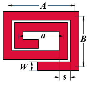 The calculation of a PCB coil with a rectangular shape of turns is based on the work of Hubert Anthony Aebischer, which can be found at the link [3] at the end of this article. The author's calculation algorithm for MATLAB in Appendix 4 has been ported to C++ for the Coil64 program. Size designations have been changed to match those of Coil64.
- W—width of the PCB trace;
- s—winding pitch (spacing);
Only an integer number of turns, at least two, is allowed. When calculating the number of turns in the “Coil” tab, it is assumed that the value of the number of turns is in the range of 2…10000. Otherwise, or if it is impossible to perform the calculation correctly, the message “Invalid combination of input parameters” is displayed. Only one internal dimension a is calculated. When calculating in the “Inductance” tab, an invalid combination of input parameters usually appears when it is impossible to fit a given number of turns in a given rectangle. It is necessary to reduce the winding pitch and, accordingly, the width of the printed conductor.
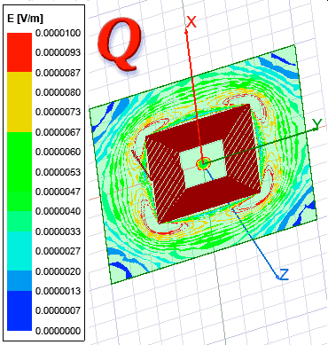 The Q-factor of a coil on a printed circuit board depends on the loss in the conductor and the loss in the substrate dielectric. The use of specialized substrates with standardized low loss is not readily available to most radio amateurs. Usual fiberglass plastic is more accessible. It has a fairly high tanδ value, and loss in the substrate have a decisive effect on the Q-factor of the coil. At the same time, unlike a microstrip line, in which there is a quasi-TEM wave concentrated mainly inside the dielectric of the substrate, the electromagnetic field of a PCB inductance coil is located both in the dielectric and in the air. For this reason, an approximate effective value of tanδ_eff should be entered in the Coil64 program, which is less than the reference values of the fiberglass loss parameter: tanδ ≈ 0.02. Obviously, such a calculation allows you to get only a very approximate value of the Q-factor, and for more accurate calculations of the quality factor of a coil on a printed circuit board, electromagnetic simulators should be used. Nevertheless, it allows taking into account in such a way the significant influence of loss in the substrate on the Q-factor. In addition, losses in the fiberglass increase with frequency and at frequencies above 150-200 MHz can reduce the quality factor of the PCB coil to unacceptably low values.
Inductor as a straight microstrip calculates by the following expression:

- L - inductance (μH)
- l -trace length (mm)
- b - trace width (mm)
Such inductive elements are often used in filters UHF band. Because of what the self-capacitance of such inductive element is quite large, it is necessary to keep in mind that the more correct to represent it in the form of a segment of a transmission line with distributed parameters. However, for approximate calculations, this model is quite acceptable if this element works at frequencies much lower the self-resonance.
Coil64 app has an additional module that allows to calculate PCB inductor with meander layout of turns.
- Simple Accurate Expressions for Planar Spiral Inductances - Mohan, S.S. ; Dept. of Electr. Eng., Stanford Univ., CA, USA ; del Mar Hershenson, M. ; Boyd, S.P. ; Lee, T.H. 1999
- Lumped Elements for RF and Microwave Circuits - Inder Bahl 2003
- Inductance Formula for Rectangular Planar Spiral Inductors with Rectangular Conductor Cross Section - Hubert Anthony Aebischer 2020;


Your PCB calculator is so great, but for some reason it is not longer available. Can you please post it up again?
Thank you so much,
Yes, right. This constant is known as the “vacuum magnetic permeability”.