Calculation of mutual inductance of two single-layer coils and a tapped coil
 When calculating LC oscillatory circuits with magnetic coupling, it is necessary to calculate the mutual inductance and the coupling coefficient between two coils. To compute the mutual inductance, the Coil64 is using the J.K. Maxwell model, in which the spiral turns of the coil are simplified as a set of coaxial infinitely thin circular conductors. The coils are meant to be formerless, therefore the winding diameters D1, D2 and winding lengths l1, l2, which are measured along the wire axes, are meant as input data. More details about this here. Both coils must be coaxial. The origin 0 in this imaginary common X axis is considered to be the beginning of the first turn of the first coil. To calculate the position of each circular filament in the calculation model, we need to know the winding pitch. The winding pitch in each coil p1, p2 is calculated as the length of the coil l1 or l2 divided by the corresponding number of turns N1 or N2. Since coils with close-winding are more often used, measuring the total length of the coil is more convenient. The offset of the second coil x is measured from the beginning of the first coil to the beginning of the second. At that, x can be less than l1. In this case, with different coil diameters, they can enter one another. The program checks that the turns of different coils do not overlap each other. In case of an error, the program displays the message “Calculation failed.”
The mutual inductance between the coils is calculated using the summation method. Using Maxwell's formula, the mutual inductance of each turn of the first coil is calculated with each turn of the second coil. The resulting values are summed. The program calculates the self-inductance of each coil and the mutual inductance. The coupling coefficient k is calculated using the formula:
 |
[1] |
where M - mutual inductance, L1, L2 - self-inductance of each of the two coils.

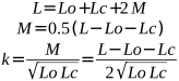
A tapped coil is often used in a parallel resonant LC-circuit to match impedances to the input/output of a transistor. Such an air coil, with N turns, can be represented as two magnetically coupled coils connected in series: a coil with nt turns before the tap, and a coil with (N - nt) turns after the tap. It cannot be considered an ideal autotransformer, and the transformation ratio cannot be calculated using the number of turns ratio, because the magnetic coupling coefficient between the coil parts is less than one and greater than zero. Therefore, we need to know the magnitude of this magnetic coupling. With a tapped coil, there is no need to calculate the mutual inductance of each pair of turns, and the calculation can be simplified.
 |
[2] |
где:
- L: self-inductance of the entire coil with the number of turns N;
- Lc: self-inductance of the part of the coil before the tap with the number of turns nt;
- Lo: self-inductance of the part of the coil after tapping with the number of turns (N - nt);
- M: mutual inductance between parts of the coil;
- k: coefficient of magnetic coupling between parts of the coil;
As can be seen from the formulas, it is enough to calculate the self-inductance of the total coil and the self-inductances of its parts.
Since the transformation ratio cannot be calculated using the turns ratio, we introduce the concept of the effective transformation ratio T. This is a dimensionless parameter that determines the ratio of voltages and currents in a tapped air core coil represented as an autotransformer model. The square of T determines the impedance transformation ratio.
 |
[3] |
The effective transformation ratio determines both the output impedance of the LC-circuit at the resonant frequency, which the transistor “sees”, and the additional loss introduced into the LC-circuit by the load resistance connected to the tap. This loss reduce the Q factor and expand the LC-circuit's bandwidth. The Coil64 program calculates these parameters for a parallel LC-tank. It should be noted that, as in the previous case, D is the winding diameter, not the former diameter.
To model two coupled coils in LTSpice, you need to know the parameters of each coil and the magnetic coupling coefficient between them, which is specified using a SPICE Directive. Coil64 can get all these parameters. A tapped coil in LTSpice is modeled as two separate, magnetically coupled coils connected in series. All the necessary parameters for this model can also be obtained from the Coil64 output field.
Related links:
- Numerical Methods for Inductance Calculation, Maxwell and Coaxial Circular Conductors - Copyright 2010, 2022, Robert Weaver;