Bandspread calculator
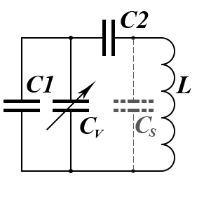
 In amateur radio practice, the problem often turns up of creating a receiver for one narrow SW band with a small ratio of the maximum frequency to the minimum. However, variable capacitors available to radio amateurs have a limited fixed set of factors of the maximum capacitance to minimum ratio. As a result, the frequency range of the LC-circuit, which includes such a capacitor, is also fixed and usually wider than necessary. At the same time, a narrow working range occupies only a small part of the receiver dial, which is very inconvenient. To stretch the working range to the full scale, you can connect in parallel and in series with the variable capacitor the so-called bandspread capacitors. Also, this idea is used for conjugation of the oscillating and input LC-circuits in superheterodyne. In this case, these capacitors named tracking capacitors. The Coil64 program allows you to calculate such capacitors.
When calculating, the initial data are the maximum and minimum capacitance of the variable capacitor Cv, as well as the minimum and maximum frequency of the working range. The value of the stray mounting capacitance Cs of the circuit layout, which is also taken into account, has a significant effect on the calculation result. With different sets of input data, two options are possible:
 The available tuning variable capacitor is not able to overlap the specified frequency range. You need to choose another one or reduce the working range.
- Frequency overlap is possible. However, it is clear that in this case the inductance value of the circuit cannot be arbitrary and is determined by the W.Thomson's formula, taking into account the possible capacitance values of all the circuit capacitors. The permissible range of inductance values is shown in a tip next to the input box.
At the reverse calculation, instead of the exact calculated capacitance values of the series and parallel capacitors, the closest from the standard E24 series are substituted. They can be selected so that the working frequency range simply fits in the receiver dial. Otherwise, both series C2 and parallel C1 additional capacitance should be made from the parallel connection of fixed and tuning capacitors to get the calculated values.
At the direct calculation, the question remains. What value of inductance should be taken from the range proposed by the program? The answer to this question depends on the appropriation of the tuned LC-circuit. If this circuit is the input circuit of the receiver, then for the minimum noise figure, and therefore for maximum sensitivity, you should create a circuit with minimal loss or with a maximum quality factor. The Q-factor of a parallel LC-circuit depends on the ratio of its characteristic impedance to the loss resistance.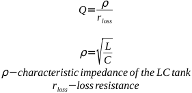
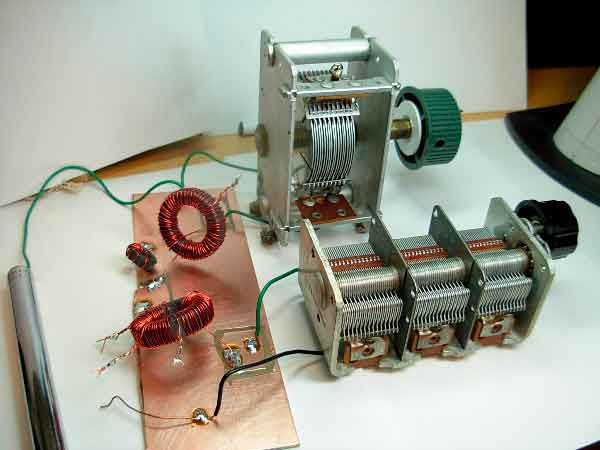 It would seem that at the maximum inductance value there will be a maximum Q-factor value, but this is not so. With maximum inductance, a large coil should be used. Loss in this case increases faster than the characteristic impedance and such LC-circuit will not have the highest possible Q-factor. The optimum, as always, is somewhere in the middle. Practitioners suggest choosing the inductance based on the LC-circuit characteristic impedance value in the range of 300 ... 500 Ohms. The Coil64 program allows you to make this choice.
If the circuit is used in a generator, then the frequency stability criterion comes first. In this case, the inductance value is recommended to choose the minimum possible, provided that the generator is stable.
The change in the tuning frequency depending on the angle of rotation of the variable capacitor is generally nonlinear. For this reason, receiver dial scales are also always nonlinear: The nonlinearity of the scale depends on the properties of the variable capacitor, as well as on the ratio of the capacities of the spreading capacitors and the inductance of the circuit. Very often, the value of the inductance of the tunable LC-circuit in old receivers was chosen based on the scale linearity criterion. The online calculator at the first link at the end of the article, in addition to calculating the spreading capacitors, draws an image of the receiver scale, which can be used to estimate its nonlinearity. The outer plates of the variable capacitor rotor are often divided into sections using slits. By bending these sections, you can adjust the nonuniformity of the receiver scale.
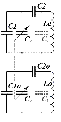 An individual case of using spreading capacitors is the tracking of the preselector and heterodyne LC-circuit tune in a superheterodyne receiver. The relation of the maximum to minimum frequency for these tunable LC-circuits is different, and the sections of the ganged variable capacitor Cv are usually identical. Therefore, in this case, it is impossible to do without using spreading (tracking) capacitors. The case when the resonant frequencies of both LC-circuits differ exactly by the value of the intermediate frequency is called zero error tracking points. Otherwise, there is a deviation of the resonant frequency of the preselector LC-circuit in one direction or another from the tuning frequency, which is called a tracking error. This leads to degradation in the sensitivity and selectivity of the receiver. It is impossible to achieve exact tracking in the whole tuning range of the variable capacitor. Depending on the initial data, exact tracking is possible at one, two or three points of the range, or is impossible at all.
The developer's task is to select such values of the capacitance of the tracking capacitors and the inductances of the RF circuit coils Le and the local oscillator circuit Lo, at which the maximum possible number of zero error points and the minimum tracking error within the tuning range are obtained. There are several methods to get these goals. The Coil64 program uses the mathematical method of V. Tsibanov's VBA program: “The Least Squares Method”. In addition to the author's method, it is possible to automatically select the RF LC-circuit inductance Le at which the minimum tracking error is attained. Since this criterion may conflict with the obtaining of other characteristics specified for this circuit, manual selection of Le within the permissible values is possible. The stray mounting capacitance Cs is assumed to be equal for both circuits. Below, as a visual example, is a graph of the tracking error within the operating range with three points of exact tracking.
If the LC-circuit inductance value is at the extreme points of the permissible range of values, then in this case it is possible to exclude the use of either a series or parallel spreading capacitor. The Coil64 does not track these cases, and the radio amateur should make a decision based on the calculated data. For example, if the capacity of the parallel capacitor is very small or the capacity of the series capacitor is very large. The exact value of the parasitic capacitance Cs is, so to speak, quite problematic to determine. The radio amateur should choose its surmised value himself. For this and not only for this reason, the calculation results should not be considered absolutely accurate, but only estimated, and in a real circuit design they will have to be corrected in any case. Nevertheless, this preliminary calculation greatly facilitates such tuning.
Reference:
- Online Bandspread Calculator - Copyright 2013, 2016 Robert Weaver;
- Bandspread Calculations. The base theory and equations - (parts 1...4) Copyright 2009, 2021 Robert Weaver;